Understand the mathematical coordinates of three dimensional space through 3D printing.
Subject: Mathematics
Aim: To understand the mathematical coordinates of three dimensional space through 3D printing.
3D printing being reliant on computing power and mathematical calculation results in interesting possibilities for combining the interest in this technology and mathematics. Three dimensional spatial graph mapping can be explored as well as the possibility for printing out 3D models to aid in spatial thinking.
Outcome: Working in a basic text editor the student is set the task of conceptualising a two dimensional profile on graph paper and transferring the coordinates to the text editor as gcode for a 3D print. Gcode is the computer language used by 3D printers. There is a beginning and end block of code that is standard to each print file. The main body of the file consists of x and y coordinates of each layer profile that then increases by the thickness of each layer in the z coordinate. So once the profile is worked out on graph paper and entered into the text editor using gcode layout then the layers can be copied and pasted with the z or height increase adjusted each layer to give the three dimensional object.
Age group: 13 years upwards
Estimated time (hours (60 minute hours): 2 hours
Resources: Graph paper, Text editor software, 3D printer.
Instructions:
1. Open Notepad/Text Editor
2. Top left = File = Open. Find ‘ MasterCode’ file that needs to be copied from below – see end of document.
3. Top left = Save As = New Name and then you must put .gcode after your file name. (Give the file your own name and then .gcode so the printer can read the file. i.e JKeep.gcode)
• No changes must be made in the block of code between the (**** start of start.gcode ****) and (**** end of start.gcode ****) and (******* End.gcode*******) and (*********end End.gcode*******). This is information given to the printer for each print
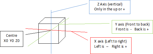
• The numbers that tell the printer where to go are typed in the body of the file. For this you use the standard three dimensional graph coordinates. (Sample file is a cube 20 x 20 x 1.1 mm)
• The numbers represent millimetres (mm) in the real world
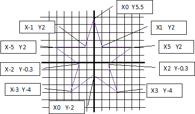
 4. First on graph paper draw the top view of the shape. The middle of the paper (X0 Y0) will be the middle of the printer
• Start at a point on your shape and write the sequence of the points on a piece of paper going around the shape. Take note you start and end on the same point so this point will be written down twice
• Transfer the points into the notepad using Z0.2 for all the Z points for the first layer. You will need to decide how big your print will be to use the correct scale when translating from the graph paper. Each layer starts with gcode M101 and ends with gcode M103. The F code is the speed the printhead moves at F810. Note: Delete the numbers for the sample cube they just offer a guide
• Copy the first layer sequence of numbers (one complete path) and paste a copy below the first in your notepad/text editor. Then make sure you add 0.3 mm to each Z point. So the second layer Z axis will all be Z0.5
• Continue piling up the shape coordinates adding 0.3 each time (Z layers read 0.2, 0.5, 0.8, 1.1, 1.4, 1.7, 2.0)
• Save your gcode file
5. Open the software that your 3D printer uses to prepare files ready for printing. Open your saved gcode file in the software. Some printers work direct from the gcode and you should be able to print. With MakerBot printer software you will need to use the Button that builds the file to SD card as this translates the gcode to a code readable by the MakerBot. This .x3g file is then what goes to the printer on the SD card.
Keywords/tags: – 3D Printing, Mathematics, 3D graph,
Alde Valley High School
Information: Jonathan Keep
MASTER CODE REQUIRED FOR PROJECT
(**** start of start.gcode ****)
M73 P0 (enable build progress)
G21 (set units to mm)
G90 (set positioning to absolute)
G10 P1 X16.5 Y0 Z-0.3 (Designate T0 Offset)
G10 P2 X-16.5 Y0 Z-0.3 (Designate T1 Offset)
G54 (Recall offset cooridinate system for T1)
M104 S215 T0 (set extruder temperature)
G162 X Y F2500 (home XY axes maximum
G161 Z F1100 (home Z axis minimum)
G92 Z-5 (set Z to -5)
G1 Z0.0 (move Z to “0”)
G161 Z F100 (home Z axis minimum)
M132 X Y Z A B (Recall stored home offsets for XYZAB axis)
G1 X105.0 Y-70.0 Z10.0 F3300.0 (move to waiting position)
G130 X0 Y0 A0 B0 (Set Stepper motor Vref to lower value while heating)
M6 T0 (wait for toolhead parts, nozzle, HBP, etc., to reach temperature)
G130 X127 Y127 A127 B127 (Set Stepper motor Vref to defaults)
M6 T0
M108 R3.0 T0
G0 X105 Y-70 (Position Nozzle)
G0 Z0.6 (Position Height)
M108 R4.0 (Set Extruder Speed)
M101 (Start Extruder)
G4 P1500 (Create Anchor)
(**** end of start.gcode ****)
(Blue code to be replaced by student. Gcode M101 and M103 must be include at the beginning and end of each layer profile. Check that the Z height increases from layer to layer. The F810 gcode is the speed the printhead will travel between coordinates. All bracketed text is not read by the printer microcomputer, it is for human reading)
M101
G1 X-10 Y-10 Z0.2 F810
G1 X10 Y-10 Z0.2 F810
G1 X10 Y10 Z0.2 F810
G1 X-10 Y10 Z0.2 F810
G1 X-10 Y-10 Z0.2 F810
M103
M101
G1 X-10 Y-10 Z0.5 F810
G1 X10 Y-10 Z0.5 F810
G1 X10 Y10 Z0.5 F810
G1 X-10 Y10 Z0.5 F810
G1 X-10 Y-10 Z0.5 F810
M103
M101
G1 X-10 Y-10 Z0.8 F810
G1 X10 Y-10 Z0.8 F810
G1 X10 Y10 Z0.8 F810
G1 X-10 Y10 Z0.8 F810
G1 X-10 Y-10 Z0.8 F810
M103
M101
G1 X-10 Y-10 Z1.1 F810
G1 X10 Y-10 Z1.1 F810
G1 X10 Y10 Z1.1 F810
G1 X-10 Y10 Z1.1 F810
G1 X-10 Y-10 Z1.1 F810
M103
(*******Begin of End.gcode*******)
M103 (Turn extruders off)
M104 S0 (Set extruder temperature to 0)
M73 P100 (end build progress )
G0 Z155
M18
M109 S0 T0
M104 S0 T0
G162 X Y F2500
M18
M70 P5 ( We <3 Making Things!)
M72 P1 ( Play Ta-Da song )
(*********End of End.gcode*******)


